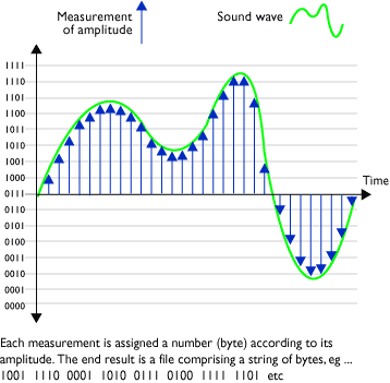
Analog And Digital Signal Diagram

Digital Vs Analog Signals Project Analog Graphic Organizers Teaching Science

Digital Vs Analog Signals Project Analog Graphic Organizers Teaching Science

An Introduction To Digital Signal Processing Digital Signal Processing Signal Processing Analog Signal

An Introduction To Digital Signal Processing Digital Signal Processing Signal Processing Analog Signal

Analogue And Digital Sound In Your Books Draw This Signal And Label It Correctly Analog Signal Digital Sound Analog

Analogue And Digital Sound In Your Books Draw This Signal And Label It Correctly Analog Signal Digital Sound Analog

Compare And Contrast Time Analogue Digital Clocks Venn Diagram Compare And Contrast Math Time Math Measurement

Compare And Contrast Time Analogue Digital Clocks Venn Diagram Compare And Contrast Math Time Math Measurement

Difference Between Digital And Analog Signals In 2020 Analog Signal Digital Signal Processing

Difference Between Digital And Analog Signals In 2020 Analog Signal Digital Signal Processing

Pin By Emily Leach On Posters Flyers Random Pics Analog Signal Digital Analog

Pin By Emily Leach On Posters Flyers Random Pics Analog Signal Digital Analog

Pin By Emily Leach On Posters Flyers Random Pics Analog Signal Digital Analog

In this article we are sharing the basic concepts of plc and dcs control systems wiring diagrams for digital input di digital output do analog input ai and analog output ao signals.

Analog and digital signal diagram. While these signals may be limited to a range of maximum and minimum values there are still an infinite number of possible values within that range. Note that these diagrams are without a barrier or isolator fuses and surge protector for keeping it very simple and understandable. In this article we comprehensively discuss how digital to analog and analog to digital converter circuits work using diagrams and formulas. Looking at a graph of a signal is usually the easiest way to identify if it s analog or digital.

The analog to digital converter adc works in the opposite way and transforms an analog input signal into a digital output. Denoted by sine waves. They need an extra source of power supply to power the circuit. Sample the sample block function is to sample the input analog signal at a specific time interval.

Uses continuous range of values to represent information. Analog signal digital signal. The main difference between analog and digital signals is analog signals are represented with the sine waves whereas digital signals are represented with square waves. Denoted by square waves.

As illustrated in the graphic. The output digital signal must be converted back into an analog signal using dac digital to analog converter if they are supposed to interact with the real world components. A digital signal is a discrete wave that carries information in binary form. In digital circuits the i p signals change from analog to digital a d form before it is processed that is the digital circuit is accomplished by processing digital signals only and generates o p which is again changed back from digital to analog signals d a so that the o p gives relevant results that can be understood by individuals.

The digital circuits can be only active circuit i e. Analog signals are continuous wave signals that change with time period whereas digital is a discrete signal is a nature. Analog signal is a continuous signal which represents physical measurements. A digital signal a must for computer processing is described as using binary 0s and 1s and therefore cannot take on any fractional values.

Digital signals are discrete time signals generated by digital modulation. An analog signal is represented by a sine wave. An analog signal is a continuous wave that changes over a time period. A digital signal is represented by square waves.

Decoder Circuit Diagram Circuit Diagram Diagram Analog Signal

Decoder Circuit Diagram Circuit Diagram Diagram Analog Signal

Analog To Digital Converter Circuit Using Adc0808 Gadgetronicx Analog To Digital Converter Digital Circuit Circuit Design

Analog To Digital Converter Circuit Using Adc0808 Gadgetronicx Analog To Digital Converter Digital Circuit Circuit Design

Difference Between Analog And Digital Signal Digital Analog Electronics Mini Projects

Difference Between Analog And Digital Signal Digital Analog Electronics Mini Projects

What Is The Difference Between Digital And Analog Signals In Electrical Engineering Analog Signal Electrical Engineering Electronics Basics

What Is The Difference Between Digital And Analog Signals In Electrical Engineering Analog Signal Electrical Engineering Electronics Basics

Pin On Science Tech Illustrated

Pin On Science Tech Illustrated

Analog To Digital Converter Files Identified Converters Profiled Analog To Digital Converter Analog Digital

Analog To Digital Converter Files Identified Converters Profiled Analog To Digital Converter Analog Digital

Analog And Digital Signal Waves Analog Waves Digital

Analog And Digital Signal Waves Analog Waves Digital

Analog To Digital Conversion Adc Analog To Digital Converter Circuit Diagram Digital

Analog To Digital Conversion Adc Analog To Digital Converter Circuit Diagram Digital

Analog To Digital Converter Analog To Digital Converter Analog Digital

Analog To Digital Converter Analog To Digital Converter Analog Digital

Sample And Hold Circuit Analog To Digital Converter Analog Signal Electronics Basics

Sample And Hold Circuit Analog To Digital Converter Analog Signal Electronics Basics

Inverting Comparator Circuit Is A Device That Compares Two Voltages Or Currents And Outputs A Di In 2020 Electronics Circuit Electrical Engineering Electronics Basics

Inverting Comparator Circuit Is A Device That Compares Two Voltages Or Currents And Outputs A Di In 2020 Electronics Circuit Electrical Engineering Electronics Basics

Planet Of Tunes How Do Audio Analogue To Digital Converters Work Analog To Digital Converter Digital Audio

Planet Of Tunes How Do Audio Analogue To Digital Converters Work Analog To Digital Converter Digital Audio

Dcs With Analog Signals Process Control Ladder Logic Piping And Instrumentation Diagram

Dcs With Analog Signals Process Control Ladder Logic Piping And Instrumentation Diagram

Introduction To Digital To Analog Converters Dac Converter Analog Digital

Introduction To Digital To Analog Converters Dac Converter Analog Digital

Source : pinterest.com
close