What Is A Schematic Diagram Explain It Use

What Is The Difference Between Schematic Diagram And Wiring Diagram For Electrical Connections Quora

Skill Builder Reading Circuit Diagrams Make
Difference Between Schematics And Circuit Diagrams
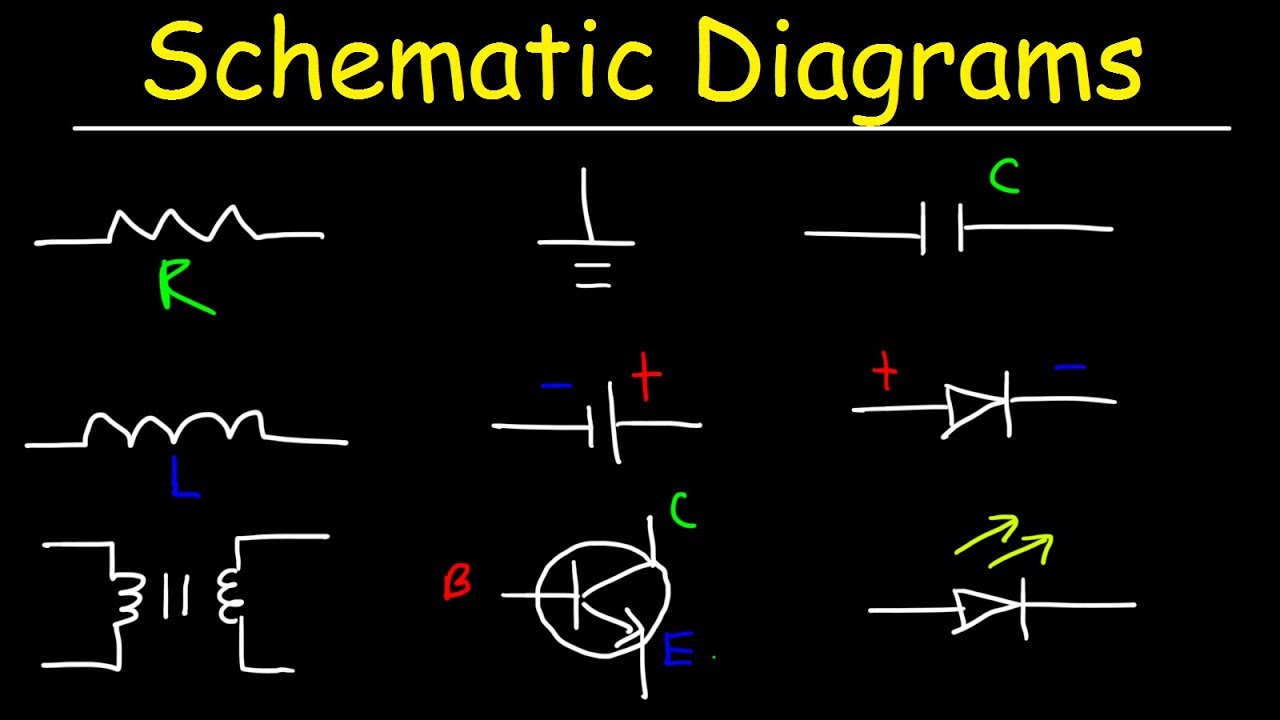
Schematic Diagrams Symbols Electrical Circuits Resistors Capacitors Inductors Diodes Leds Youtube
How To Make A Schematic Diagram In Coreldraw
Electrical Schematic Symbols Study Com

Erd diagrams are commonly used in conjunction with a data flow diagram to display the contents of a data store.
What is a schematic diagram explain it use. A purpose of use case diagram is to capture core functionalities of a system and visualize the interactions of various things called as actors with the use case. A schematic diagram focuses more on comprehending and spreading information rather than doing physical operations. The use case diagrams represent the core parts of a system and the workflow between them. This is the general use of a use case diagram.
The presentation of the interconnections between circuit components in. It basically describes the state change of a class interface etc. Although schematic diagrams are commonly associated with electrical circuits many examples can be found in other industries. A schematic diagram of a chemical process uses symbols in place of detailed representations of the vessels piping valves pumps and other equipment that compose the system thus emphasizing the functions of the individual elements and the interconnections among them and suppresses their particular physical details.
Bar graphs are used to show relationships between different data series that are independent of each other. State chart diagram is used to visualize the reaction of a system by internal external factors. Schematic diagrams can also differ in their level of abstraction. A schematic diagramis a picture that represents the components of a process device or other object using abstract often standardized symbols and lines.
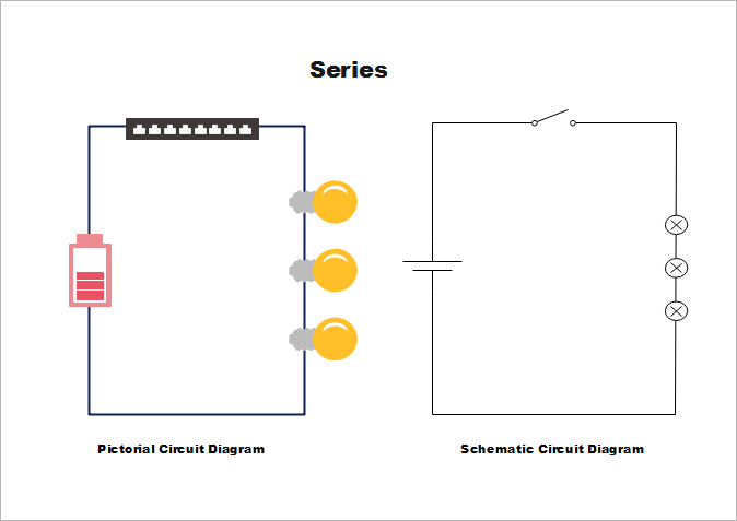
Class diagram describes the attributes and operations of a class and also the constraints imposed on the system. A diagram is a symbolic representation of information using visualization techniques. Entity relationship diagram tutorial here are some best practice tips for constructing an erd. A circuit diagram electrical diagram elementary diagram electronic schematic is a graphical representation of an electrical circuit a pictorial circuit diagram uses simple images of components while a schematic diagram shows the components and interconnections of the circuit using standardized symbolic representations.
A schematic or schematic diagram represents the elements of a system with abstract and graphic symbols instead of realistic pictures. They help us to visualize how data is connected in a general way and are particularly useful for constructing a relational database. Statechart diagram is used to represent the event driven state change of a system. Diagrams have been used since ancient times on walls of caves but became more prevalent during the enlightenment.
In this case the height or length of the bar indicates the measured value or frequency. The 4 main types of graphs are a bar graph or bar chart line graph pie chart and diagram.
Electronics Components Integrated Circuits In Schematic Diagrams Dummies
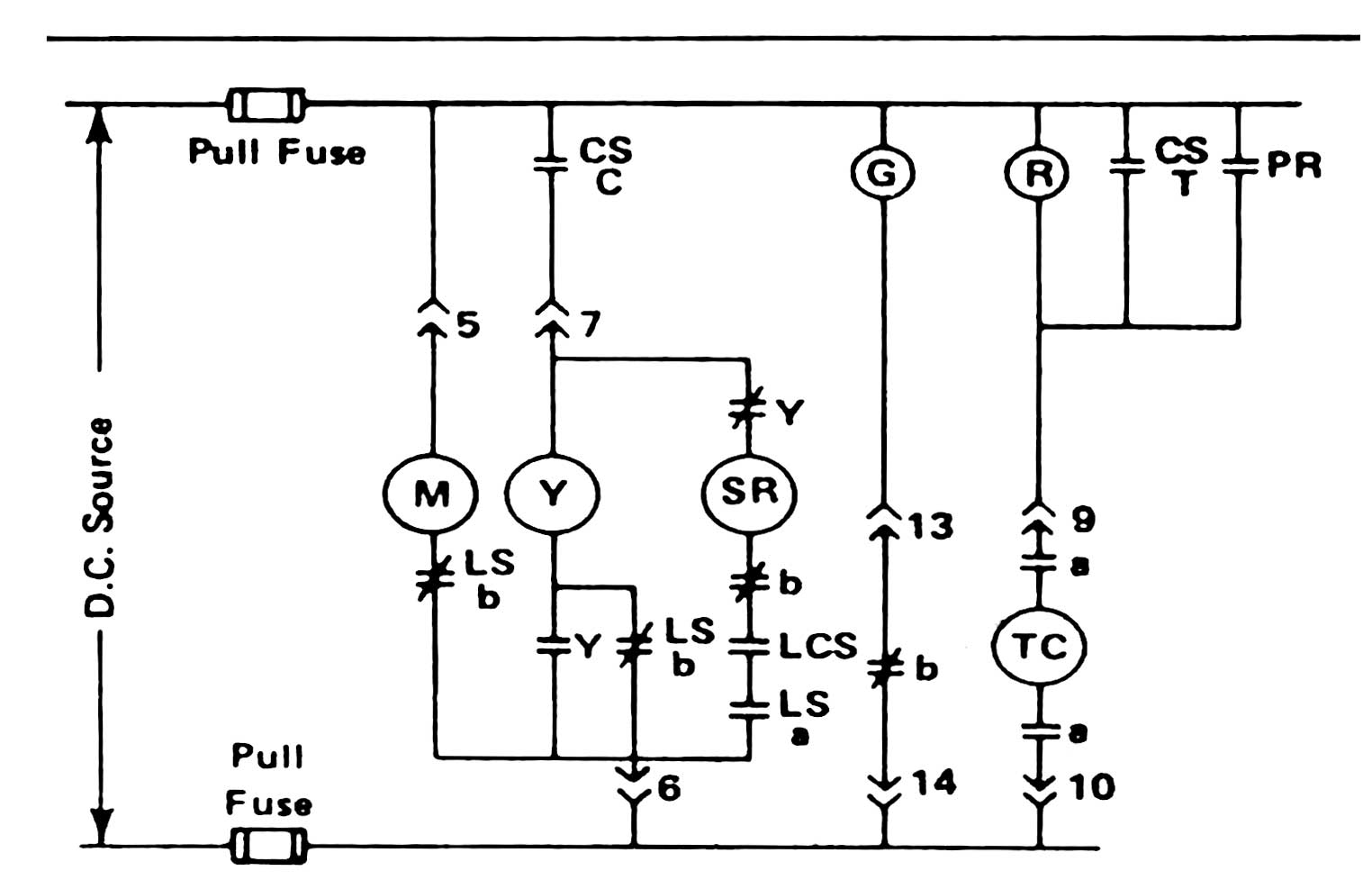
Circuit Breaker Control Schematic Explained

Schematic Diagrams An Overview Sciencedirect Topics

Pin On Amplificador

Schematic Diagram Of Heat Engine Di 2020

The Circuit Diagram Of A Mosquito Repellent Power Saver Circuit Is Given With A Detailed Explanation Electronics Circuit Power Saver Circuit Diagram

Ecosystem Diagram Fig 1 Schematic Diagram Indicating The Different Ecosystem States Ericaceous Plants Ecosystems Fig
Circuit Schematic Electronics Electronics Circuit Electronic Circuit Projects Electrical Circuit Diagram

3 High Power Sg3525 Pure Sinewave Inverter Circuits Homemade Circuit Projects In 2020 Circuit Projects Electronic Circuit Projects Circuit

The Schematic Diagram Of The Induction Heater With Igbt S Induction Heating Circuit Diagram Induction

Simple Code Locker Circuit Using Cd4017 Lockers Circuit Simple Code

Two Stroke Engine Schematic Diagram Di 2020

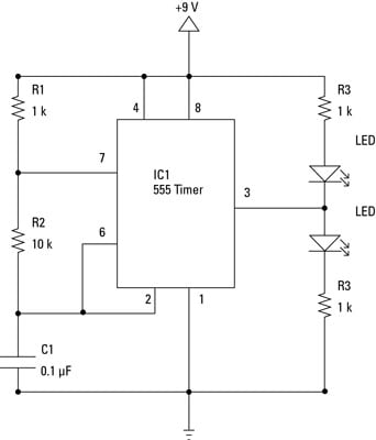
Led Flasher Using Timer Ic 555 Enviremenralb Com Elektronika


