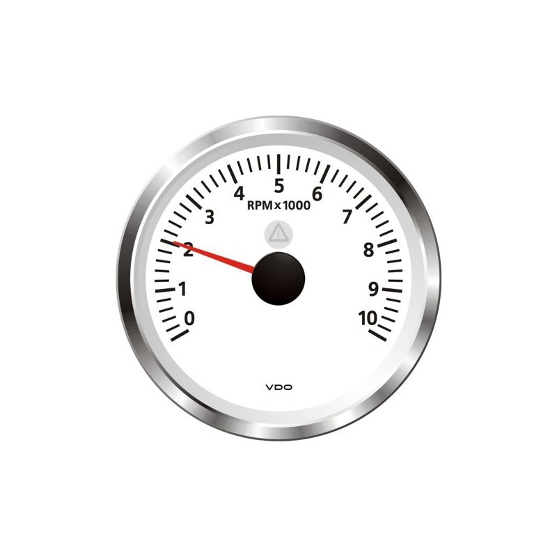
Vdo Viewline Tachometer Wiring Diagram

Procedures for installing vdo viewline instruments.
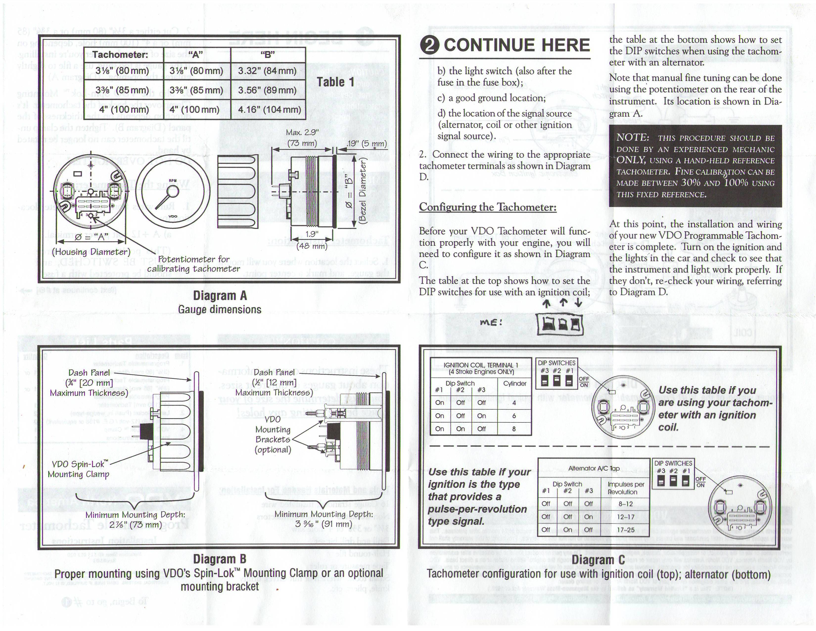
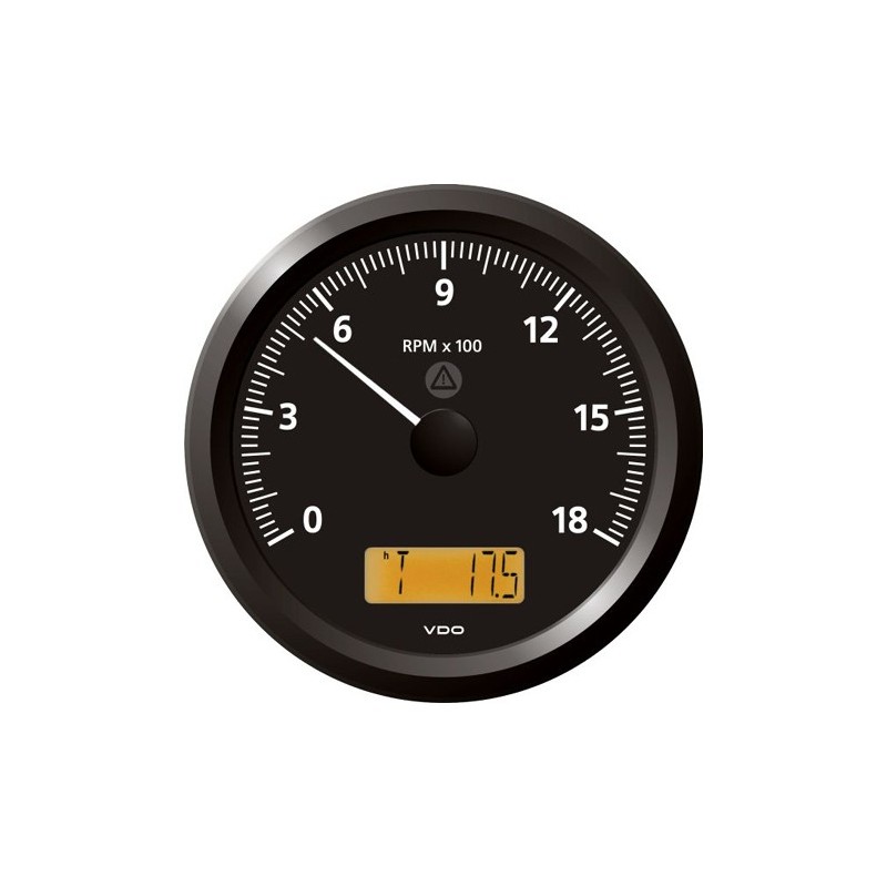
Vdo viewline tachometer wiring diagram. Vdo water temp gauge see more like this. Viewline 52 mm temperature gauge pressure gauge rudder angel gauge. Vdo tachometer installation manual manualzz performance instruments and operations instructions rg 1989 rpm gauge wiring diagram 63842 tach small library tacho dip switch settings sel tuli hole gmm koblenz de for an o b page 2 boat design net faria fuel e27 auto electrical electric sdometer with odometer schematic vdo tachometer installation manual manualzz vdo performance instruments. You may also mount the tachometer using an optional vdo mounting bracket and nuts.
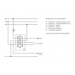
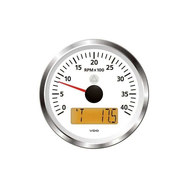
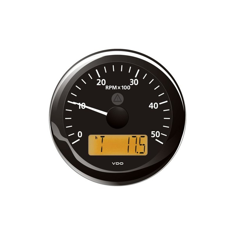
Vdo tachometer installation manual faria wiring e30 performance instruments 1b5 electronic sdometer gauge diagram also sk 2627 a2c53436982 rev counters auto tach wo 8283. Vehicle application list 34 pages summary of contents for vdo tachometer. 8 pin connection f1 fuse 5a quick response c1 8 pin mqs connector. Viewline tachometer without lcd 12 startup setting the impulse number imp r switch 1 switch 2 switch 3 xxx 0 0 0.
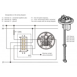
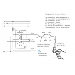
Make sure all wires are long enough to reach the necessary positive and negative terminals and any wires from the sensor. Vdo viewline wiring diagram another graphic. Viewline 85 mm tu00 0752 5807102 1 10 4 technische änderungen vorbehalten technical details subject to change tu00 0752 5807102 tachometer gb 30 terminal 30 steady state plus 12 v 15 terminal 15 connected ignition plus 58 terminal 58 lighting 31 terminal 31 ground designations in the wiring diagram. Diagram g wiring diagram wiring of power and ground to each gauge illumination wiring.
Measuring instruments vdo viewline tachometer product information 4 pages measuring instruments vdo contisys obd quick reference manual 59 pages measuring instruments vdo contisys obd application list v2 0 manual. Prepare insulated spade terminals for use with the tachometer. Mounting the tachometer 1. Installation instructions viewline 52 mm vdo com according to the electrical wiring diagram if operating the instrument on power supply units note that the power supply unit must be.
If operating the instrument on power supply units note that the power supply unit must be stabilized and it must comply with the. The ohm range of the sender and the gauge must match. 88565 333 055b vdo tachometer wiring diagram library. Shown in diagram c.
According to the electrical wiring diagram. F c water temperature gauge use with vdo sender 12v spade connection learn more viewline ivory f c water temperature gauge 12 24v. Viewline onyx fuel gauge 12 24v use with 3 180 ohm sender vdo. Procedures for installing vdo viewline instruments.
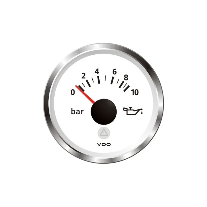
Designations in the wiring diagram. Viewline 52mm wiring diagram 2014 viewline mechanical water pressure gauge 2011 viewline pressure gauges 12 24 volt 2011 viewline pressure gauges 52mm 2008 viewline standard resistive gauges 52mm installation sheet 2014 vision cockpit mechanical pressure datasheet 2003 vision cockpit pressure temperature volt gauge data sheet 2003.
