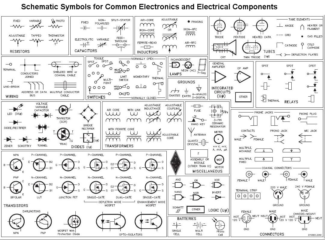
Schematic Diagram Symbols And Meaning

The symbols represent electrical and electronic components.
Schematic diagram symbols and meaning. Physical er models show all table structures including column name column data type column constraints primary key foreign key and relationships between tables. As you are into the workspace of edrawmax drag the symbol that you need directly onto the canvas. There are hundreds of different types of electronic components and each has its own unique schematic diagram symbol. Making an electrical diagram becomes easy when you have access to thousands of electrical templates and symbols at your fingertips.
Yourdon and coad and gane and sarson. A schematic diagram is a picture that represents the components of a process device or other object using abstract often standardized symbols and lines. Schematic diagrams only depict the significant components of a system though some details in the diagram may also be exaggerated or introduced to. Table of electrical symbols.
This guide will walk you through the process of making a mathematical venn diagram explaining all the important symbols along the way. Electrical symbols and electronic circuit symbols are used for drawing schematic diagram. Simple electronic circuits can have as little as two components. Venn diagrams represent mathematical sets.
With the standard electrical symbols in edraw you can create a circuit diagram that shows the actual layout of the components simply and quickly. A schematic is defined as a picture that shows something in a simple way using symbols. They are mostly used to draw a circuit diagram and are standardized internationally by the ieee standard ieee std 315 and the british standard bs 3939. Note that when used.
Most electronic circuits will have additional components. What are the symbols used in data flow diagrams dfd. There are two different types of approaches to symbols in data flow diagrams. Fortunately you need to know only a few basic symbols and labels to get you started.
Electrical symbols electronic symbols. Click the icon of basic electrical to open the stencil that includes all symbols for making circuit diagrams. In the yourdon and coad way processes are depicted as circles while in the gane and sarson diagram the processes are squares with rounded corners. In electronic circuits there are many electronic symbols that are used to represent or identify a basic electronic or electrical device.
Electrical symbols are standardized throughout the industry so it is easy to achieve the ability to interpret the meaning of the symbols.


