Motor Control Schematic Symbols

Schematics and wiring diagrams are the written language of motor controls.
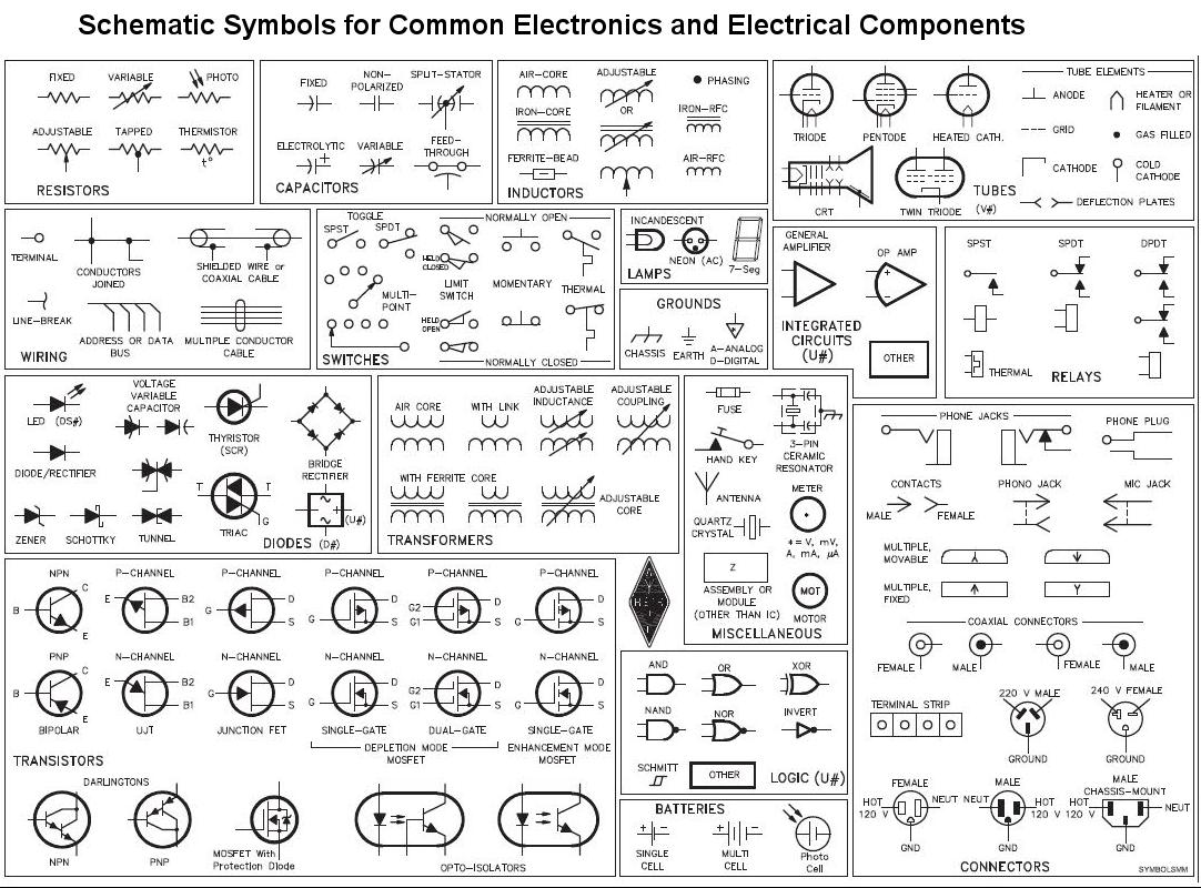
Motor control schematic symbols. One line diagrams are used when information about a circuit is required. Before you can learn to properly determine the logic of a control circuit you must first learn the written language. This is the symbol of a generic electrical motor that is used in electrical schematics. The course discusses schematic symbols.
Schematic symbols is part four of the motor controls eight part training series. Basic wiring for motor control technical data. Line diagrams show circuits of the operation of the controller. Circuit symbols the following are the circuit symbols commonly used in motor related schematic diagrams.
The manner in which symbols are drawn and interpreted will be discussed. These panels may be small as shown in figure 2 or very large as required to house the necessary. Figure 1 typical wiring diagram. Students will be introduced to the differences between symbols used to represent electrical and control components.
Motor whose field winding is in series with the armature winding is called dc series motor it is represented by this symbol in schematic designs. A motor converts electrical energy into mechanical energy. Starter power control and wiring diagram. Rockis 2001 one line diagrams one line diagram a diagram that uses single lines and graphic symbols to indicate the path and components of an electrical circuit.
Panel wiring techniques electrical control panels are available in all shapes and sizes to suit the particular requirements of the situation. Figure 1 is a typical wiring diagram for a three phase magnetic motor starter. This set of symbols is called the alphabet.


