3 Wire Speed Sensor Crank Sensor Wiring Diagram

I am having similar problems on my 91 ram l cummins according to the wiring diagrams the diesel and gasser tanks have the same wires coming off the sending unit but one of the wires has dissimilar functions on a gasser it goes to the fuel pump on a diesel it.
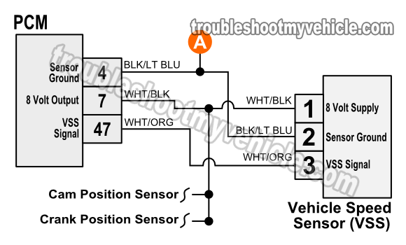
3 wire speed sensor crank sensor wiring diagram. Replaced crankshaft speed sensor and situation didn t change. Disengage the wiring harness connector from the vss. Knock sensor wiring diagram get rid of wiring diagram problem pdf p0019 crankshaft position camshaft position bank 2 sensor pdf part 2 how to test the 24x crank sensor gm 3 1l 3 4l pdf. Sensor signal wire is a tn yl wire goes from pcm to cam sensor tn yl is tan with yellow tracer sensor ground and 5 v supply are as above but instead of crank sensor insert cam sensor.
Crank sensor wiring diagram wiring diagram images gallery pdf how to test a wheel speed sensor in under 15 minutes pdf related file of nissan speed sensor wire diagram. Both wires connect the vss to your vehicle to ground the sensor and transmit information about you re vehicle s speed. This is a image galleries about 3 wire hall effect sensor you can also find other images like wiring diagram parts diagram replacement parts electrical diagram repair manuals engine diagram engine scheme wiring harness fuse box vacuum diagram timing belt timing chain brakes diagram transmission diagram and engine problems. 4 crankshaft position sensor wiring diagram you should pay attention to crankshaft position sensor symptoms.
Wiring diagram for horn turn signal kit included. Crank position speed sensor fits polaris ranger crew.


